Below should be everything you need to know in order to make a KTRL 64 gamepad. It all comes down to these steps: Get the needed parts, prepare the gamepad case, solder the components, program the microprocessor* and finally, put it all together.
*) or get the microprosessor preprogrammed from me.
I have designed the PCB to fit the cheap SNES style USB gamepads available on eBay and elsewhere. There are a few different models out there but the best ones I have found for this are the iNNEXT branded ones. They look like this:

This gamepad comes in black and gray. Search for "innext snes" on eBay and you should find several sellers selling these, usually in packs of two for about 7€ and up plus shipping.
I have been using Sega Mega Drive gamepad extension cables for this, those have all 9 pins connected (all 9 are needed for this gamepad). I just cut the male connector off. These can also be found on eBay of course (and other places). Search for "sega genesis extension" on eBay and you should find several. The price can be as low as 2.20€/cable

You can order the PCBs from me on Amibay.com. I sell the main PCB plus the PCB for the two button adapter as a package.

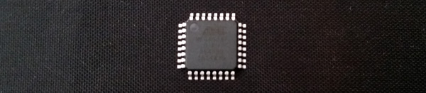
The microprocessor used by the KTRL 64 is the Atmega328P-AU (TQFP-32 package). You can buy this from eBay, electronic component retailers or buy them preprogrammed from me on Amibay.com.
I also sell the other electronic components needed in the same Amibay.com thread as a set. Here is the list of other components if you want to get them from somewhere else:
| 0805 SMD components | |
| 2K2ohm (222,2201) | 1 |
| 10kohm (103,1002) | 1 |
| 100nF (104) | 1 |
| Through hole components | |
| 47µF electrolytic cap 16V | 1 |
| LED (red, 3mm, flat top) | 1 |
| Other parts | |
| Wire, red, ~6cm | 1 |
| Wire, black, ~6cm | 1 |
| Pin headers (2,54mm pitch) | 6 |
| Shrink tube, dia: 4mm, length: 6mm | 1 |
| For two button adapter | |
| Wire, black, ~8cm | 1 |
| 9-pin DSUB connector, male | 1 |
| 9-pin DSUB connector, female | 2 |
| Shrink tube, dia: 19mm, length: 20mm | 1 |
| 9-pin DSUB casing (3D printed in kit) | 1 |

The "KTRL 64" logo and cheat sheet stickers are included when you buy the PCBs in the Amibay.com thread.

To program the Atmega you will a USBAsp programmer. These are very cheap and available readily on eBay. Search for "usbasp" and you should find them for less than 2€. For this you also need Dupont jumper wires (Female-Female). Search on eBay for "dupont male female". Note that if you buy the Atmega preprogrammed from me you don't necessarily need this but I might release updates to the firmware later.

Unscrew the five screws of the gamepad to open it and remove all the parts. You will need the small shoulder button PCBs connected to the main PCB so don't throw anything away just yet.
Optional but recommended: Drill a 3mm hole for the LED in the top part of the case according to the picture below. You don't need to install the LED but it helps with configuring the controller.

Optional: Remove the face button sticker (with the A,B,X,Y markings). I have found that the best way to do this is to use a hair dryer to heat up the sticker (for about 10-15 seconds, don't overdo it if you have a powerful hair dryer), then the sticker usually peels off without leaving any residue on the gamepad case.
Optional: Apply the stickers. The logo sticker can cover the "iNNEXT" logo entirely. The cheat sheet sticker goes to the back (in the recessed area).
Solder the the PCB components according to the following layout (Click the picture to view a larger version). The only SMD capacitor is 100nF and in the kit it us unmarked and light brown in colour.


1. Bend the legs of the LED 90° about 5mm from the actual LED and cut the legs about 5mm after the bend, leaving the longer leg about 1mm longer so you still know which leg is which.
2. Solder a red wire to the longer leg and a black wire to the shorter leg.
3. Use the heat shrink tube to cover the solder joints.

4. Solder the wires to the PCB, red to LED+ and black to LED-. The wires go to the back side of the PCB as seen in the picture below for the KTRL CD32. (The pins for the LEDs on the KTRL 64 are closer together.)

Remove about 35mm of the sleeve of the cable, and remove a few millimeters of the sleeve of every wire. Use a multimeter to figure out which wire goes to which pin. The table below shows cable colors for cables acquired from eBay with codes 4N40011, AAJ104895001 and VG0006450. It's recommended that you double-check this using a multimeter.
Ensure the correct pin numbers (marked on the main PCB) when soldering the cable. Failing to do so could cause damage to the KTRL gamepad or your C64!

| Pin | 4N40011, AAJ104895001, VG0006450 |
| 1 | RED |
| 2 | BLACK |
| 3 | GRAY |
| 4 | ORANGE |
| 5 | BROWN |
| 6 | GREEN |
| 7 | WHITE |
| 8 | BLUE |
| 9 | YELLOW |


